Adobe Illustrator (Ai) - Tutorial 2
Tracing Technical Drawings
Difficulty: Medium
What you will learn: Pen tool, bezier, layers, stroke and fill, brush basics, patterns, width tool, text tool
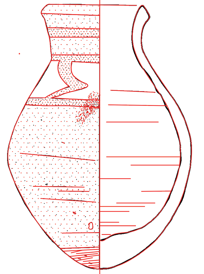
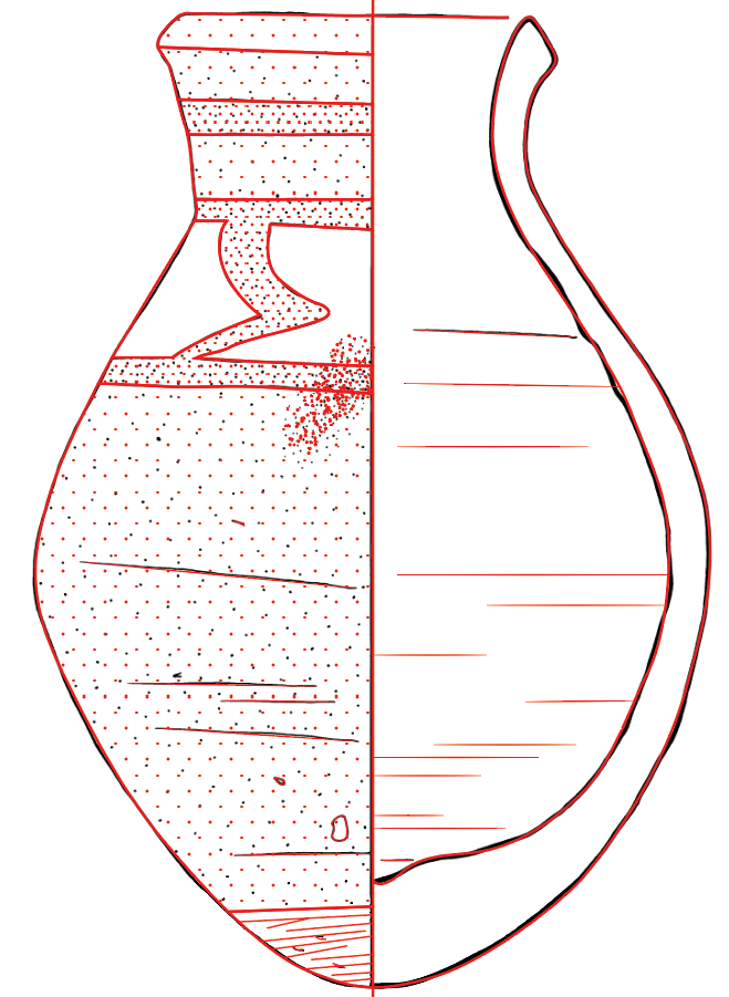
Download this reference image: TNE96_219 Reference Image
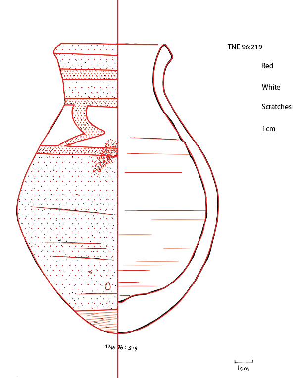
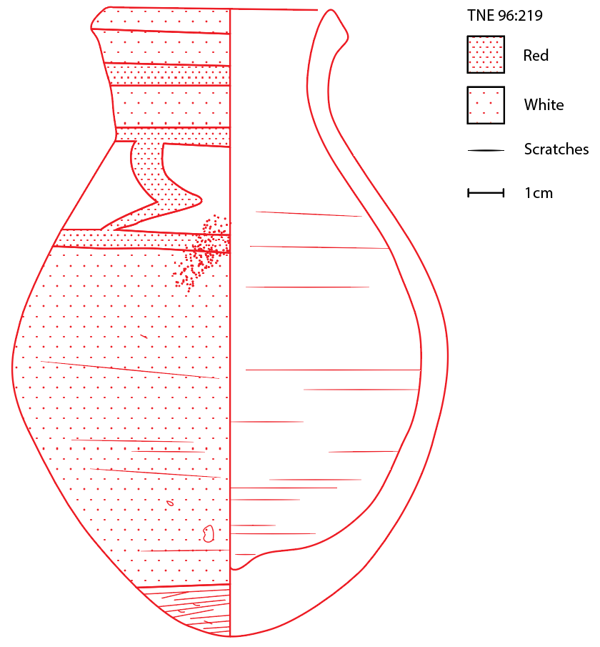
Result:
Step 1 - Creating a new Illustrator document
Open Adobe Illustrator.
Click on Create New.
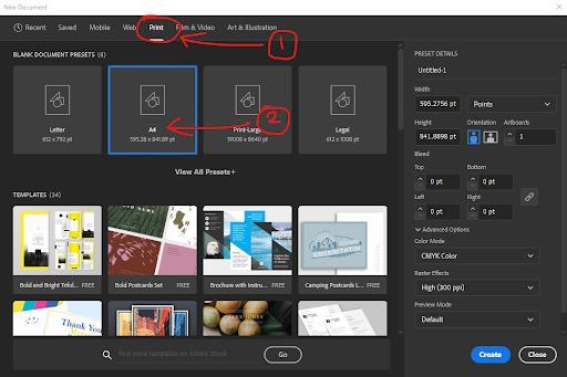
Click on Print > A4, then click on the blue button called Create. This will create a new document for you to work on.
Step 2 - Reference image
Download TNE96_219 Reference Image at the top of the page.
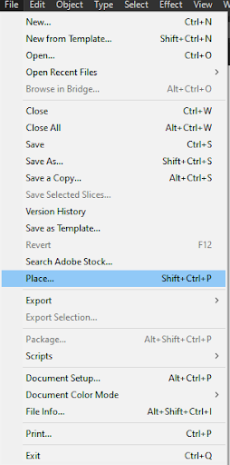
Go to File > Place, select and import the reference image.
Rename Layer 1 to Reference by double-clicking on the name of the layer.

How to use the pen tool
The Pen Tool (P) is located on the toolbar on the left side of the screen. Pressing P on your keyboard will also select the Pen Tool.
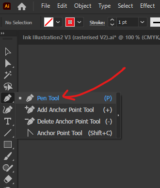
Clicking on the artboard with the Pen Tool will create new anchor points which are used to create the path.

After starting a path, press Esc to end the path.

Holding left-click and dragging will create an anchor point with a bezier applied to the path.
Holding Option (Windows - hold Alt) and left-click dragging on one of the branches extending out of the anchor point will allow you to edit the bezier curve.
Holding Command ⌘ (Windows - hold Ctrl) and left-click dragging on the anchor points will allow you to edit the location of the anchor points.

To continue editing an existing path, use the Pen Tool (P) to click on the anchor point at the end of the path.
Step 3 - Creating a guide layer
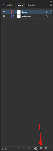
Create a new layer by clicking on the Create New Layer icon ![]() . Rename the new layer to Guide.
. Rename the new layer to Guide.
Select the Pen Tool (P) and ensure the Guide layer is selected. Left-click at the top centre of the artboard to start a path. While holding Shift, left-click at the bottom of the artboard to create a path that is snapped vertically. To finish the newly created path, press Esc.
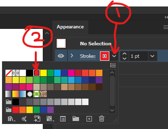
Note: your newly created path may appear invisible as there is no stroke applied to the path. To fix this, go to Appearance > Stroke > select the drop-down icon > select Red.
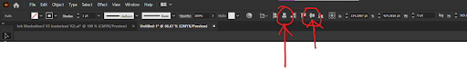
With the vertical line selected, select Horizontal Align Centre and then Vertical Align Centre to centre the vertical line to the centre of the artboard.
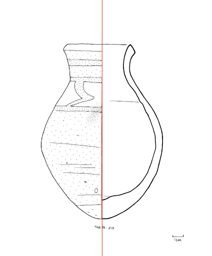
Select the reference image and align the image with the vertical line. It should look like this:
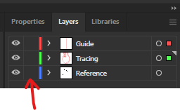
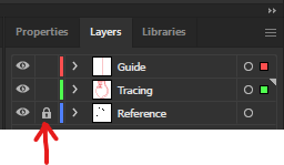
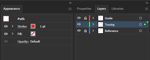
Lock the Reference layer in the Layers panel to avoid accidentally making changes to the reference image layer. A layer that is locked is indicated by the padlock icon and can be activated by clicking on the empty space shown in the images below.
Step 4 - Tracing the edge of the vase
With the Tracing layer selected, use the Pen Tool (P) to begin tracing the outside of the vase.
In the Appearance panel, change the colour of the stroke to red, increase the stroke width to 1pt and ensure that fill is set to none.
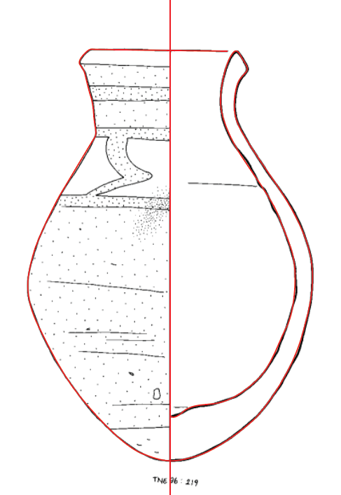
Results should look similar to this:
Step 5 - Tracing the edges of the vase patterns
With the Tracing layer still selected, use the Pen Tool (P) to trace the vase patterns.
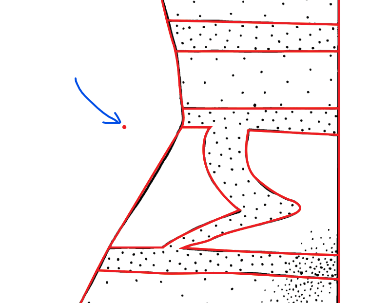
Results should look similar to this:
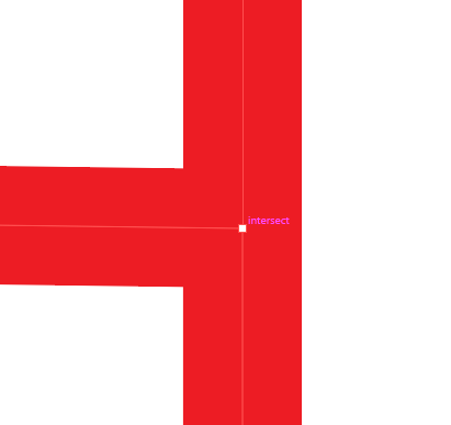
Note: With tracing lines that intersect with each other in the reference image, ensure that the start of a path is snapped to the other path. With the Pen Tool (P) selected, hovering over an existing path will cause a prompt to indicate that the creation of an anchor point will snap to the path. Ensuring that each path is snapped to each other is important for the next step where we will build shapes using the paths that have been created.
The snap-to-path prompt will look like this:

Step 6 - Shape builder tool
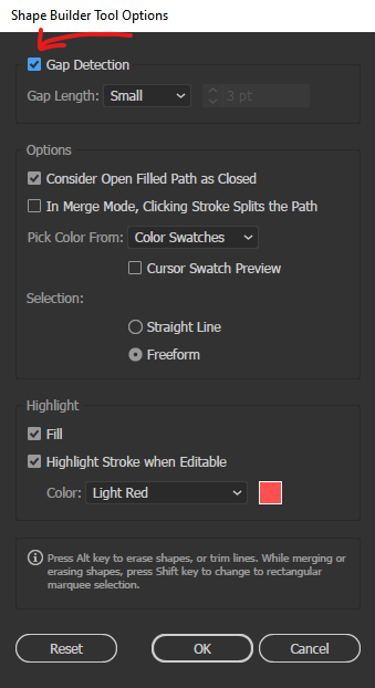
Double-click on the Shape Builder Tool icon on the toolbar, located on the left side of the screen. This will bring up the Shape Builder Tool Options pop-up window. Ensure that the Gap Detection box is checked and press OK to close the window.
The Shape Builder Tool icon looks like this:
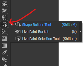
Select the Shape Builder Tool (Shift + M) on the toolbar.
Press Command ⌘ + A (Windows - Ctrl + A) to select all paths.
Hovering the cursor over regions will fill these spaces with a grey translucent pattern. This indicates that the filled area will be converted into a shape if clicked.
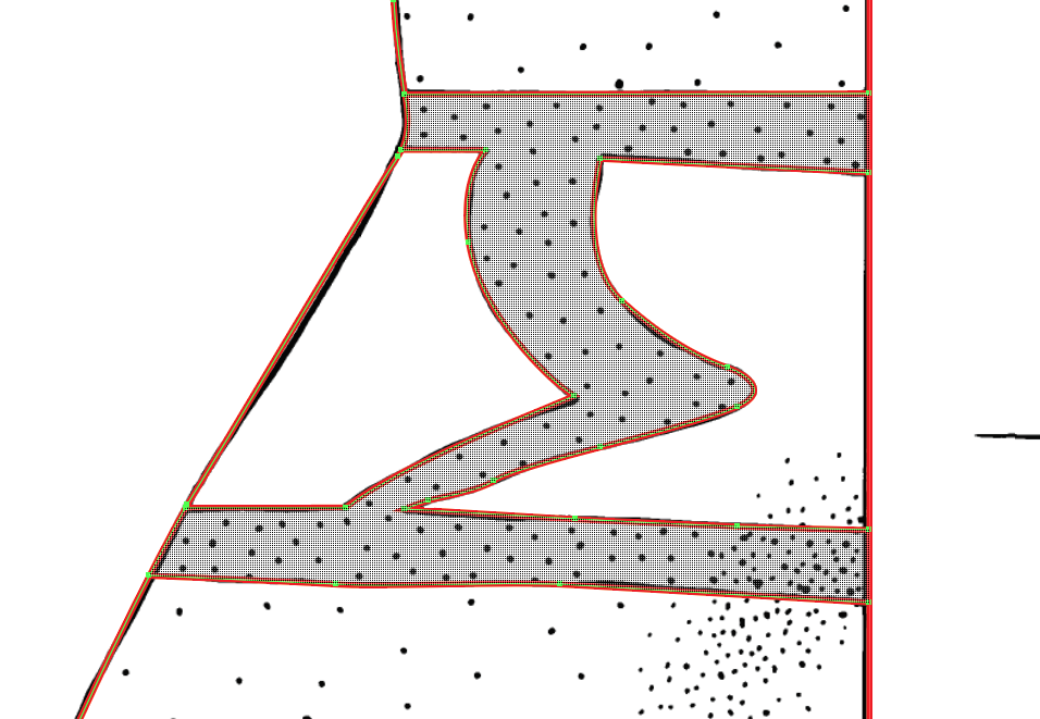
Convert areas with stippling into shapes so they can be filled with a pattern.
Step 7 - Creating a sample dot for the pattern
We will now be creating a sample dot which will be used to create the stipple pattern. It will look something similar to this:
Create a new layer ![]() and rename it to Pattern.
and rename it to Pattern.
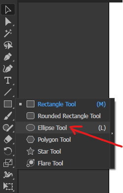
Right-click on the Rectangle Tool on the toolbar and select Ellipse Tool. Or press L on your keyboard to use the Ellipse Tool (L).
With the Pattern layer selected, use the Ellipse Tool (L) and hold Shift while click-dragging on an empty area of your artboard to create a symmetrical circle. Scale the circle to roughly the same size as the stippling in the reference image. Holding Shift will snap the scaling to be uniform.
In the Appearance panel, set the stroke to none and fill to red.
Step 8 - Creating the dotted pattern
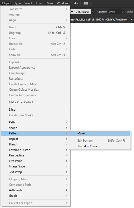
With the sample red dot selected, go to and select Object > Pattern > Make.
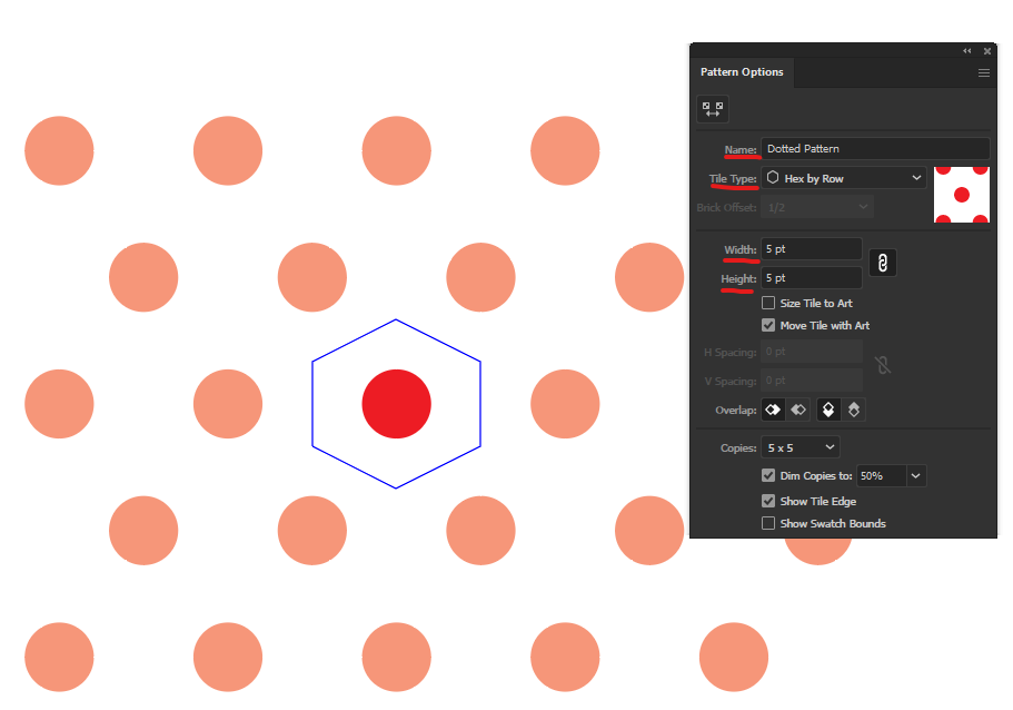
In the Pattern Options window, rename the pattern to Dotted Pattern.
Change Tile Type from Grid to Hex by Row.
Change Width and Height to 5pt.
The settings should look similar to this:
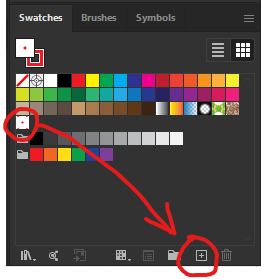
In the Swatches panel, duplicate the dotted pattern by dragging the first dotted pattern onto the New Swatch icon ![]()
Double click on the duplicated pattern to open up the Pattern Options window.
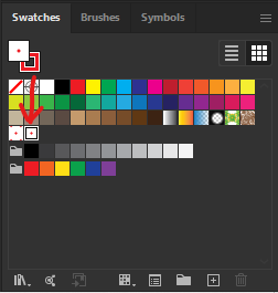
Rename the pattern to Dotted Pattern 2.
Change the Width and Height to 10pt.
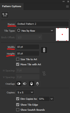
Close the window.
Step 9 - Filling the shapes using the dotted pattern
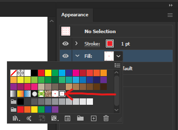
Using the Selection Tool (V), select the shapes you would like to fill by clicking on the edge.
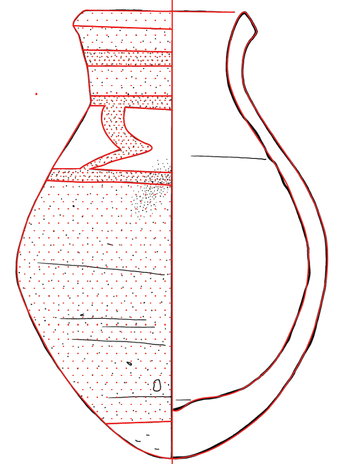
In the Appearance panel, change the fill to either Dotted Pattern or Dotted Pattern 2 depending on the stippling density as shown in the reference image. Repeat until all the necessary shapes have been filled.
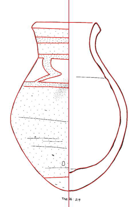
Results should look similar to this:
Step 10 - Creating a dotted brush
With the sample dot selected, go to the Brushes panel and click on the New Brush icon ![]() .
.
Note: The Brushes panel is on the same panel as Swatches.
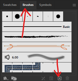
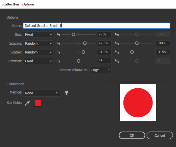
Choose Scatter Brush and press OK. The Scatter Brush Options window will appear.
Rename the brush to Dotted Scatter Brush 1 and change the settings to match the image below. Press OK once done.
Step 11 - Using the dotted brush
Create a new layer ![]() and rename it to Details.
and rename it to Details.
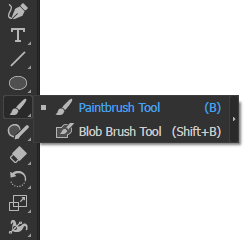
Select the Paintbrush Tool (B) on the toolbar, located on the left side of the screen or press B.
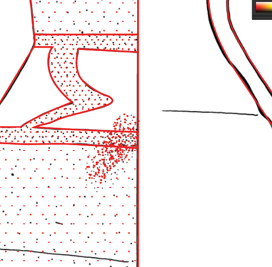
With the Dotted Scatter Brush 1 which you created, paint the dots in the centre of the vase illustration. Continue painting with the dotted scatter brush until it resembles the reference image.
Results should look similar to this:
Step 12 - Additional scratch details
With the Details layer selected, use the Pen Tool (P) to trace any remaining reference image details which has not been copied yet.
Results should look similar to this:
Note: In the image above, additional detail was added to the illustration (this detail is not on the reference image) and is not necessary to copy.
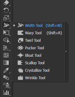
Step 13 - Using the width tool
Some strokes on the reference image have different widths, most notably at the ends where they taper off instead of having abrupt ends. So we will try to replicate this.
Select the Width Tool (Shift + W) from the toolbar.
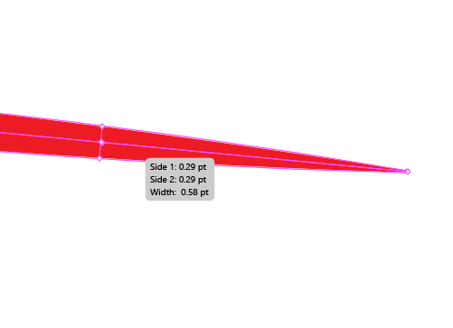
Select a path and click-and-drag anywhere on the path to add an anchor point so that it can be used to edit the width of the path.
Adding an anchor point to the end of the path and one near the end can be used to taper the width of the path.
Example:
An alternative method is to go to the Variable Width Profile on the top toolbar and select Width Profile 1.
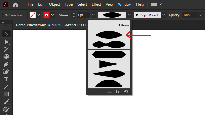
Repeat and change the widths of all the necessary strokes to match the reference image.
In the Appearance panel, change the stroke of the scratches in the Details layer to 0.5pt.
Results should look similar to this:
Step 14 - Creating the legend
Create a new layer and rename it to Legend.
With the Legend layer selected, select the Type Tool (T) on the toolbar.
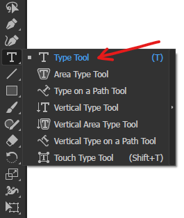
Click on an empty space on the right side of the illustration to create a text box.
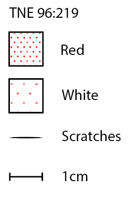
Create individual textboxes for the words: TNE 96:219, Red, White, Scratches and 1cm.
The textbox can be edited by selecting the textbox with the Type Tool (T) once or double-clicking on the textbox with the Selection Tool (V).
Results should look similar to this:
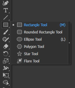
To create the key graphics, use the Rectangle Tool (M) on the toolbar and hold Option (Windows - Hold Alt) while click-dragging to create a square.
Create a square for Red and White and place them adjacent to the respective labels. Change the stroke to Black for both squares and change the fill to Dotted Pattern (the denser dotted pattern) for Red, meanwhile Dotted Pattern 2 for White (the less dense dotted pattern).
Use the Pen Tool (P) to create a short horizontal stroke adjacent next to the Scratches label. Use the Width Tool (Shift + W) to taper the ends of the stroke or set the Variable Width Profile to Width Profile 1.
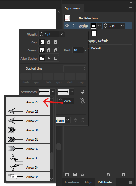
Again, use the Pen Tool (P) to create a short horizontal path adjacent to the 1cm label. In the Appearance panel, go into the stroke options and change the Arrowhead to Arrow 27 for both sides. Ensure that the length of the 1cm key matches the length of the reference image.
Results should look similar to this:
Step 15 - Trimming the vertical guideline
Select the Scissors Tool (C) by right-clicking on the Eraser Tool (Shift + E) icon tool to access it.
Hold Option (Windows - hold Alt) and use the scroll wheel to zoom in at the point of intersection between the vase and the vertical guideline. Hovering the cursor over the point of intersection will highlight an anchor point. Clicking on the anchor point with the Scissors Tool (C) will separate the path into two different parts.
Once the path has been divided, select and delete the excess parts of the vertical path below and above the illustration.
Results should look similar to this:
Step 16 - Changing the colours to black
Using the Selection Tool (V), click and drag to select every red-coloured stroke. (Note: don't forget to select the red-coloured pattern in the key).
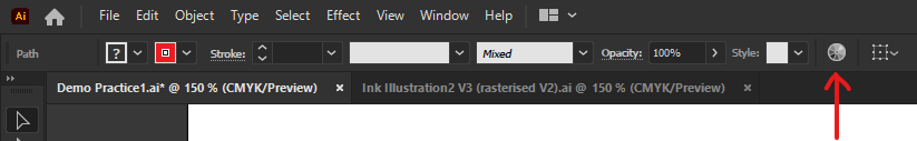
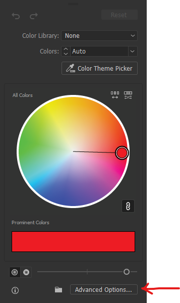
Once every red-coloured stroke has been selected, select the Recolour Artwork option to bring up a colour wheel window.
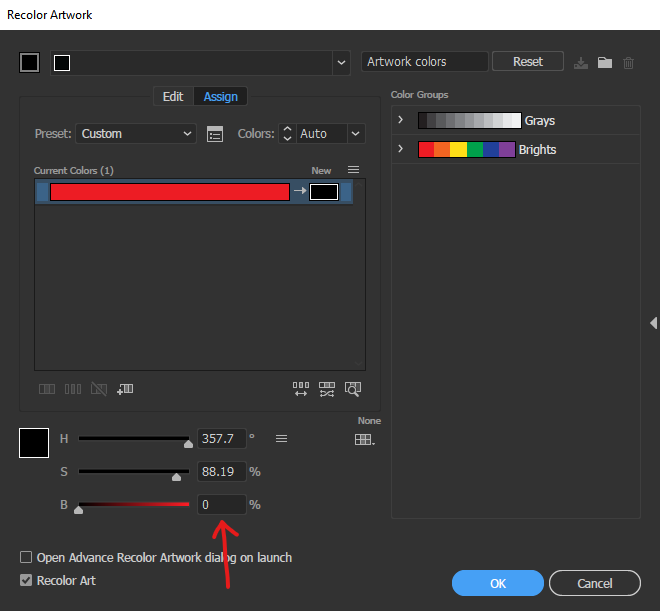
Next, select Advanced Options to bring up a new window.
Change this value to 0% to turn the colour into Black. Next, press OK.
Step 17 - Expanding
Create a new copy of the document file by going to File > Save As and save the new file somewhere in your storage. This is done to create a backup file just in case you need to revert back to an old save as the next steps are destructive.
Select everything by pressing Command ⌘ + A (Windows - Ctrl + A).
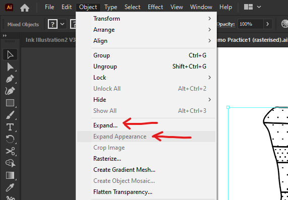
Next, go to Object > Expand Appearance.
Reselect everything by pressing Command ⌘ + A (Windows - Ctrl + A) again.
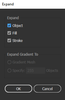
Next, go to Object > Expand. Ensure that Object, Fill and Stroke is checked, then hit OK.
This process will convert the paths into shapes and minimise the occurrence of artifacts when we export the illustration in a .SVG format.
Note: You may have to Expand again as it may not convert the text paths into shapes the first time.
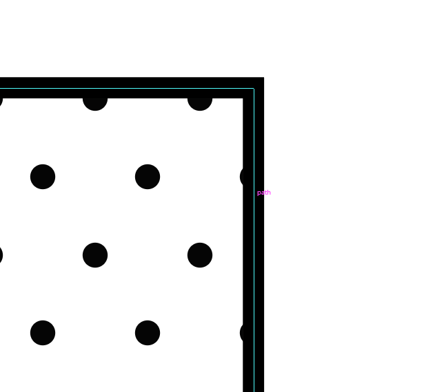
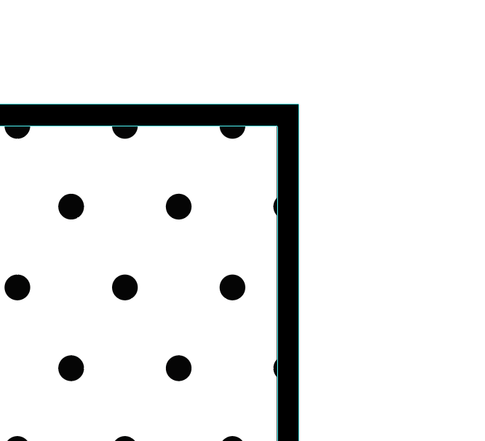
Example:
Before Expand After Expand
Step 18 - Exporting
Go to File > Export > Export As.
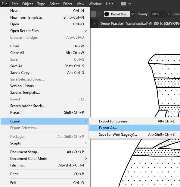
Ensure that the file is exported as .SVG and then press Export.
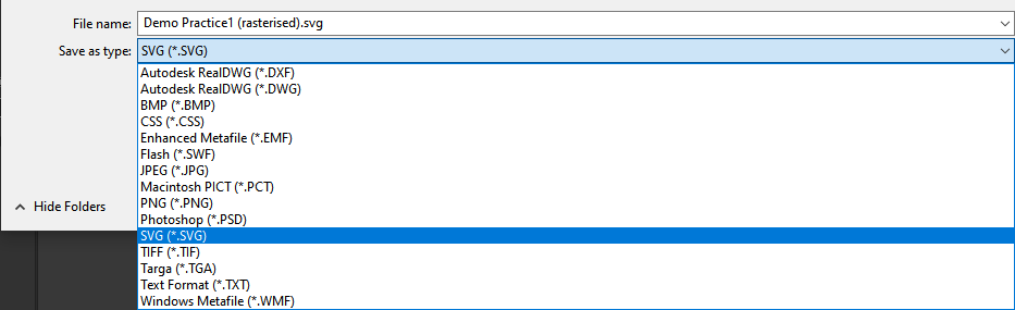
A new window called SVG Options will appear. Leave the settings as default and hit OK.
Awesome job, you've finished it! 🙂