Adobe Illustrator (Il) - Tutorial
10 essential things to get started with in Illustrator
Difficulty: Easy
What you will learn:
- File formats
- AI
- EPS
- SVG
- Selection tools
- Selection tool
- Direct selection tool
- Paths
- Bezier curves
- Stroke and fill
- Stroke
- Fill
- Layers
- Layers
- Grouping
- Locking
- Hiding
- Pathfinder
- Shape Modes
- Clipping masks
- Building shapes
- Shape Builder Tool
- Scissor Tool
- Text tool
- Text properties
- Guides
- Guidelines
- Snapping
- Align
- Distribute
- Integrating images
- Placing images
1) File Formats
These file formats are called native formats meaning that all Illustrator data is preserved when the file is saved.
To save a document as any of these four formats, go to File > Save As... and change the Save Type To to its respective file type.
AI
.AI is the format used to save Adobe Illustrator documents. All Illustrator data is saved and preserved when this file type is used. This file type allows the document to be saved and then reopened in the future to continue editing or making changes to the document.
AI only supports vector graphics.
.AI is the recommended file type to use to save your Illustrator files.
Note: under Save Type To, the AI format is named Adobe Illustrator (*.AI).
EPS
.EPS stands for Encapsulated PostScript and is a legacy vector graphic format. EPS is usually used for print workflows or saving a preview of a design.
EPS supports both vector and bitmap images.
EPS does not support transparency.
This file format can be used to view images digitally, however, isn't fully optimised and lacks some features compared to SVG as this format is older.
Note: under Save Type To, the EPS format is named Illustrator EPS (*.EPS).
SVG
.SVG stands for Scalable Vector Graphics and is a vector images format that is XML-based.
SVG is the standard format used to publish vector graphics on the web and can be animated.
SVG can be converted into HTML code which can be pasted into a webpage to publish.
SVG supports vector graphics and bitmap images, however, these images are embedded into the file.
Note: under Save Type To, the SVG format is named SVG (*.SVG).
.PDF stands for Portable Document Format and is used to view or display documents.
PDF supports both vector and bitmap images.
Note: under Save Type To, the PDF format is named Adobe PDF (*.PDF).
2) Selection Tools
There are two types of selection tools which include the: Selection Tool (V) and Direct Selection Tool (A).
Selection Tool
The selection tool is used to select or move entire objects or paths. The tool icon is a black arrow ![]() and pressing V can be used as the hotkey to use it.
and pressing V can be used as the hotkey to use it.
Direct Selection Tool
The direct selection tool is used to modify shapes or paths. The tool icon is a white arrow ![]() and pressing A can be used as the hotkey to use it.
and pressing A can be used as the hotkey to use it.
The direct selection tool can also be used to select a single object in a group.
Note: think of the selection tool as a blunt selection tool and the direct selection tool as a more precise selection tool.
3) Paths
Using the pen tool
The Pen Tool (P) is located on the toolbar on the left side of the screen. Pressing P on your keyboard will also select the Pen Tool.
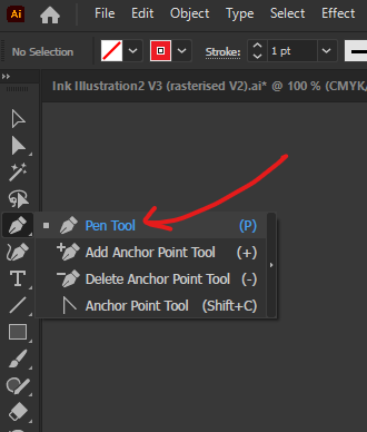
Clicking on the artboard with the Pen Tool will create new anchor points which are used to create the path.

After starting a path, press Esc to end the path.

Holding left-click and dragging will create an anchor point with a bezier applied to the path.
Holding Option (Windows - hold Alt) and left-click dragging on one of the branches extending out of the anchor point will allow you to edit the bezier curve.
Holding Command ⌘ (Windows - hold Ctrl) and left-click dragging on the anchor points will allow you to edit the location of the anchor points.

To continue editing an existing path, use the Pen Tool (P) to click on the anchor point at the end of the path.
4) Stroke and Fill
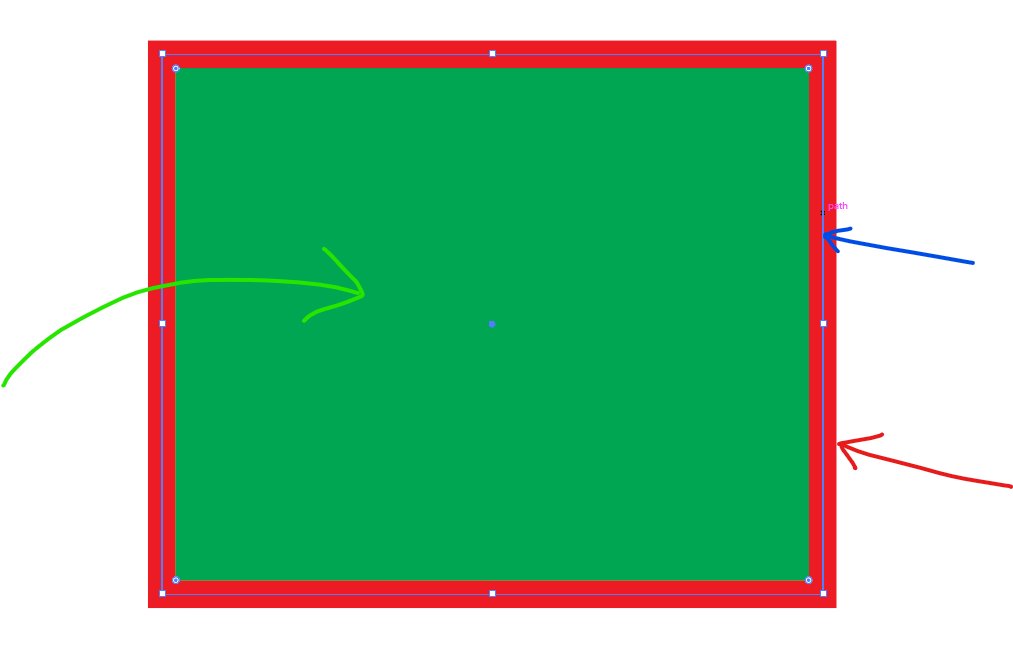
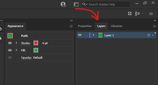
Stroke is the colour, width or style of a path. The stroke is the red border of the shape in the image above (red arrow).
Fill is the area enclosed in a shape or path. The fill is the green filling of the shape in the image above (green arrow).
Path is a vector-based line. The path is the thin blue line in the centre of the stroke and runs along the edges of the shape (blue arrow). It controls the direction of the stroke.
Stroke and fill properties can be accessed via the Control or Properties panels. If these panels are absent within your workspace, you can show them by going to Window > Control or/ Properties.
Stroke
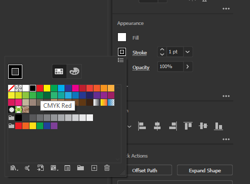
With a path or shape selected, go to the Properties panel and select the Stroke thumbnail. This will bring up a swatches drop-down menu which can be used to select the colour of the stroke.
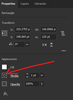
Left-clicking on the Stroke text (where the red arrow points to) will bring up another drop-down menu that shows the settings of the stroke.
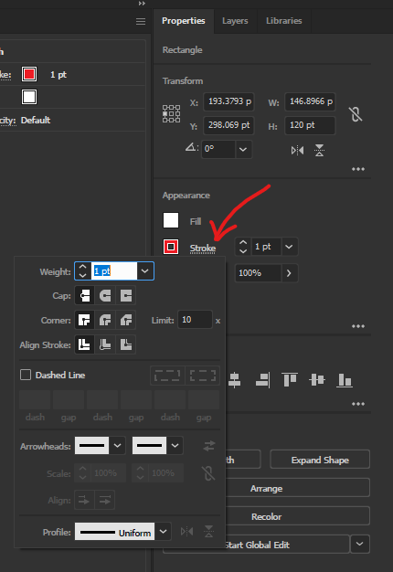
Weight is the width of the stroke.
Cap changes the end caps of the strokes to be rounded or offset.
Corner changes if the corners are sharp, rounded or slanted.
Align Stroke changes the offset of the path from the edges/centre of the stroke.
Dashed Line changes the stroke into a bee trail/marching ants.
Arrowheads change the end caps to arrowheads.
Profile changes the width profile of the stroke (if the ends of the stroke are tapered off or not).
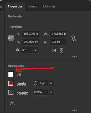
Fill
Left-clicking on the thumbnail of Fill will bring up a swatches drop-down menu which can be used to select the colour of the fill.
5) Layers
Layers can be used to organise and isolate different elements of your document.
The Layers panel neighbours the Properties panel on the right side of the workspace.
If the Layers panel is absent, it can be accessed by going to Window > Layers.
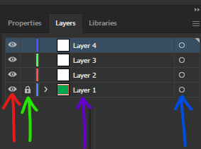
Left-clicking on the eye icon (red arrow) will show/hide the layer.
Left-clicking on the padlock icon (green arrow) will lock/unlock the layer. Locking a layer means that objects within the layer cannot be selected or edited.
Note: layers are set to unlock by default which means the icon will be invisible, hence, maybe the reason why you won't be able to see it. Left-click on the empty space to activate the padlock.
Double left-clicking on the name of the layer (purple arrow) will edit the name.
Left-clicking on the circle icon (blue arrow) will select every object within that layer.
Grouping
Grouping helps organise your document and allows multiple objects to be edited at once.
Select multiple objects using the Selection Tool (V). (Selecting multiple objects can be achieved by left-clicking and dragging across a range of objects or holding Shift and left-clicking on specific objects you would like to group.
Once your desired objects have been selected, go to Object > Group to group your selection of objects.
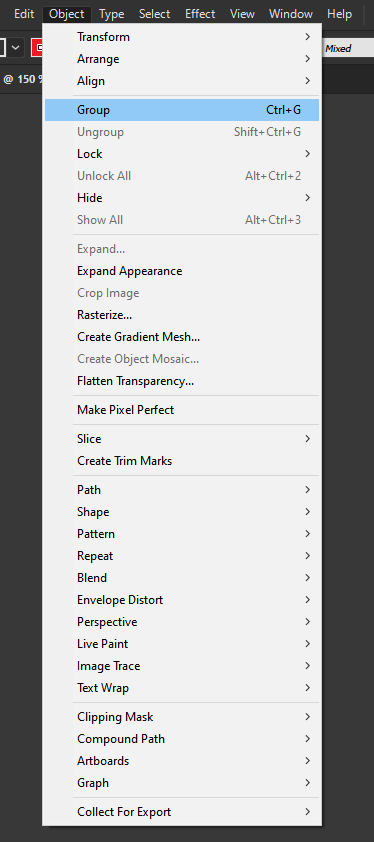
Note: to ungroup your selection, have your group of objects selected and go to Object > Ungroup. (Ungroup is underneath Group in the Object drop-down menu).
6) Shape Building
Shape Builder Tool
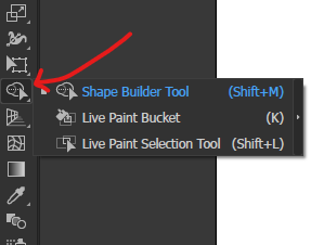
The Shape Builder Tool (Shift + M) can be used to build shapes from paths.
The Shape Builder Tool can be accessed from the toolbar on the left and the icon looks like this:
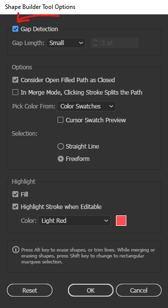
The Gap Detection setting will be enabled for Illustrator to recognise joining paths as closed shapes.
Double left-click on the Shape Builder Tool icon to open its settings. Tick the checkbox for Gap Detection to enable the feature and then hit OK to close the window.
Note: other settings should be left at default. Other than the Gap Detection checkbox being ticked, the other default settings should look like this:
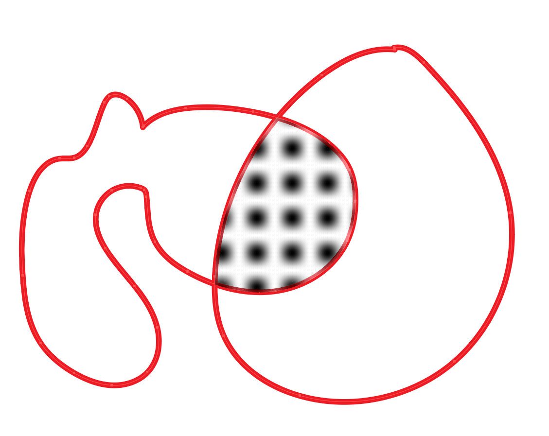
Important: the Shape Builder Tool will only work on selected objects, therefore, select the objects you would like to convert from paths to shapes.
With the Shape Builder Tool, hovering over empty areas of the selected objects will cause a checked pattern to appear. This indicates that left-clicking on this highlighted area will convert the region into a shape. For example, in the image below, the Shape Builder Tool is hovered over the enclosed path and fills the region with a checked pattern. Left-clicking to convert the area into a shape will create a new shape on top of the existing paths.
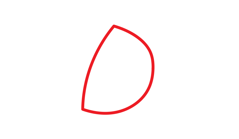
After the path has been converted into a shape:
Scissor Tool
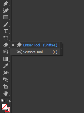
The Scissor Tool is used to split a path.
The Scissor Tool (C) can be accessed by right-clicking on the Eraser Tool from the toolbar to show a drop-down menu with additional tools.
Using the Scissor Tool, left-clicking on a path will split it.
Before:

After (the path on the left side has been deleted to show that the path has been split):


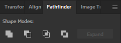
7) Pathfinder
Pathfinder can be used to merge or subtract different shapes from each other to be able to create new compound shapes.
There are four main Shape Modes that can be used to change the interaction between shapes: Unite, Minus Front, Intersect, Exclude.
Important:
- By default, the pathfinder panel is not shown. To show this panel, go to Window > Pathfinder to enable the panel.
- The pathfinder will only be applied to selected objects.
The example that will be used in the demonstrations below:
Note: The blue circle is in front of the red circle.
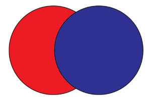
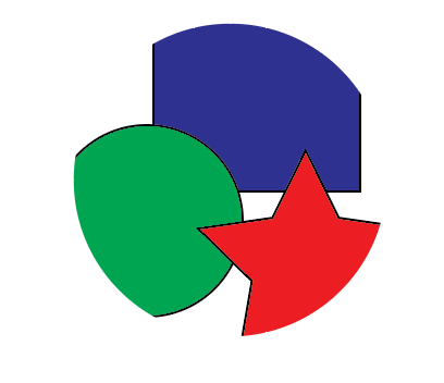
Unite
Merges both objects together. The properties of the bottom object will be converted to the properties of the front object.
Before: After unite is applied:
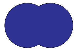
Minus Front
Subtracts the bottom object shape from the shape of the front object.
Before: After minus front is applied:
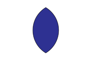
Intersect
Only the overlapping region is left behind.
Before: After intersect is applied:
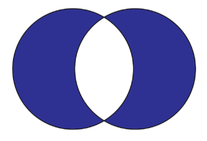
Exclude
The overlapping region is eliminated and the original shapes is left behind.
Before: After exclude is applied:
Clipping Masks
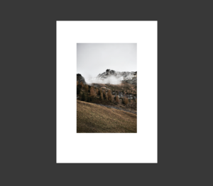
Clipping masks can be used to hide or show specific parts of your shape or image.
To create a clipping mask, have your image/shape as the bottom object.
Next, create your mask which can be any shape or path.
Important:
- Ensure that your mask is at the front (the mask should be on top of the image to create a clipping mask).
- Ensure that the mask is white as any other shades or colours will affect the results.
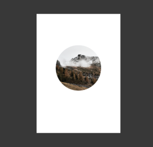
In the image below, the circle shape is placed on top of the image and will be used as the mask:
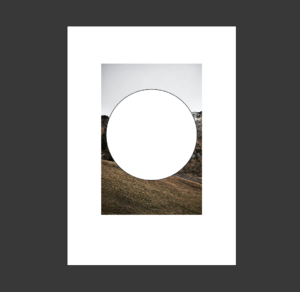
Next, with both the image and mask selected, go to Object > Clipping Mask > Make which will create the clipping mask.
The results:
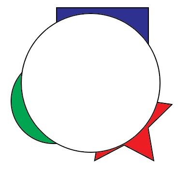
Clipping masks can also be used on groups of objects.
In the example below, the rectangle, circle and star shapes are grouped together.
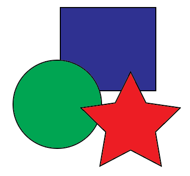
With the white circle mask on top of it, using a clipping mask will also work.
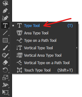
8) Type Tool
Select the Type Tool (T) from the toolbar on the left side of the workspace.
A textbox can be created by left-clicking anywhere on the artboard or left-clicking and dragging across the artboard.
To start editing the text in the textbox, left-clicking on the textbox with the Type Tool or double left-click on the textbox with the Selection Tool.
To exit the text editing mode of the textbox, left-click outside the textbox or press Esc.
Text properties can be accessed via the Control or Properties panel.
Control
![]()
Properties
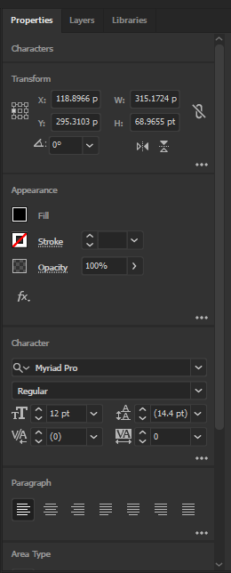
Text Properties
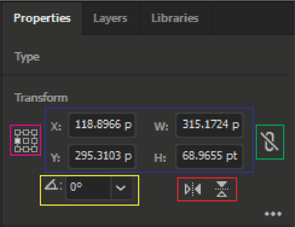
Transform
Blue - dimensions of the object
Green - maintain the width and height proportions
Magenta - where the reference point of the object is set to
Yellow - the rotation of the object
Red - flip the object on the vertical or horizontal axis
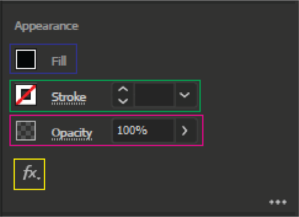
Appearance
Blue - changes the colour of the fill. Left-clicking on the thumbnail will bring up a swatches menu to select the colour the fill.
Green - changes the colour of the stroke. Left-clicking on the thumbnail will bring up a swatches menu to select the colour of the stroke. The width of the stroke can be changed in the right box.
Magenta - changes the opacity. The percentage of the opacity can be changed in the right box. 0% is invisible and 100% is visible.
Yellow - additional effects can be added to the object/text.
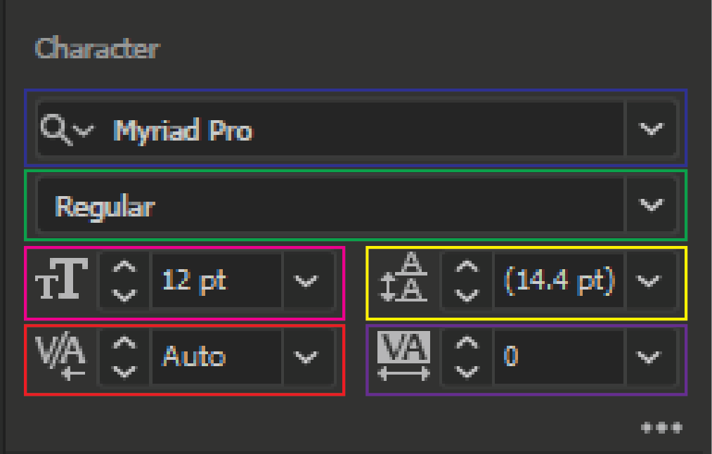
Character
Blue - the font family.
Green - the font type (e.g. italic, bold).
Magenta - the font size.
Yellow - the leading of the font (the spacing in between lines).
Red - the kerning of the font (the spacing between two characters).
Purple - the tracking of the font (the spacing between every character).
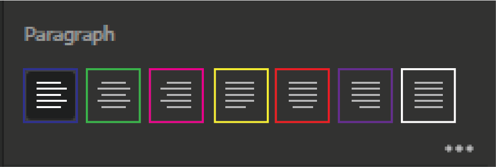
Paragraph
Blue - align paragraph to the left.
Green - align paragraph to the centre.
Magenta - align paragraph to the right.
Yellow - the paragraph is justified aligned to the left.
Red - the paragraph is justified aligned to the centre.
Purple - the paragraph is justified aligned to the right.
White - the paragraph is justified aligned.
Note: justified alignment causes the text to be aligned to the margin of the textbox.
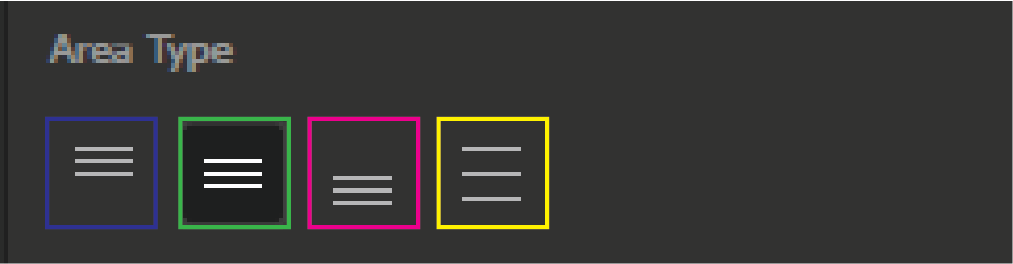
Area Type
Blue - align paragraph to the top of the textbox.
Green - align paragraph to the centre of the textbox.
Magenta - align paragraph to the bottom of the textbox.
Yellow - evenly distribute the paragraph vertically in the textbox.
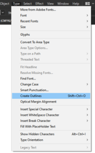
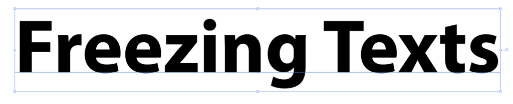
Freezing Text
Freezing texts rasterise it into shapes, meaning that the text will no longer be editable and all changes will be permanent.
To freeze text, select it and then go to Type > Create Outline.
Before using Create Outline:
After using Create Outline:
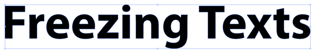
After using Create Outline, a faint blue outline will appear around the text indicating that the letters are now individual shapes. The paths of each letter can also now be modified.
Using the Direct Selection Tool (A), select a letter can left-click and drag on an anchor point to move it and modify the shape of the letter.
With the Direct Selection Tool activated:

After using the Direct Selection Tool to modify the paths of the letters:

9) Guides, Snapping, Align and Distribute
Guidelines
Enable the ruler by going View > Rulers > Show Rulers.
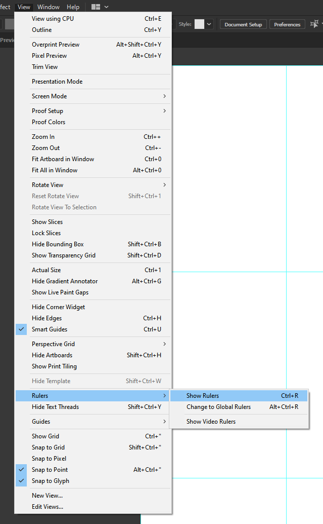
Enable Snap to Grid by going to View > Snap to Grid.
If Smart Guides are disabled, go to View > Smart Guides to re-enable it.
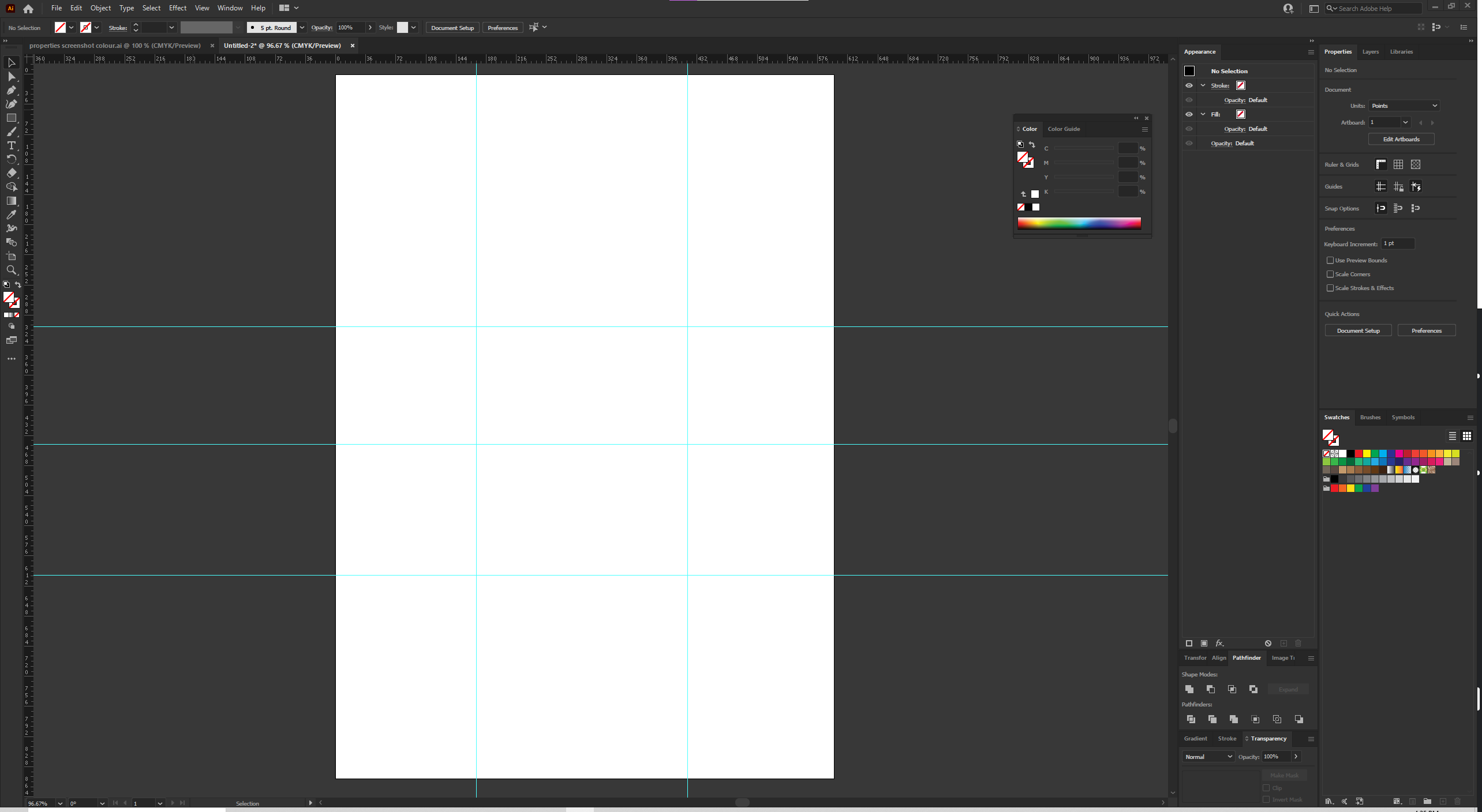
The ruler will appear at the edge of the workspace on the top and left sides of the screen. The ruler will look like this:
![]()
Left-clicking on this ruler and dragging it will create a guide.
- Left-clicking and dragging from the top ruler will create a horizontal guide.
- Left-clicking and dragging from the left ruler will create a vertical guide.
The guidelines can be custom made and will look similar to this:
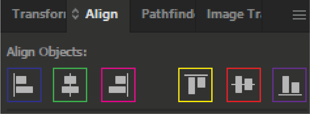
Align
The Align panel can be used to align objects to other objects or features.
The align features can be used via the Align or Properties panel.
To access the Align panel, go to Window > Align.
Blue - horizontally aligns to the left.
Green - horizontally aligns to the centre.
Magenta - horizontally aligns to the right.
Yellow - vertically aligns to the top.
Red - vertically aligns to the centre.
Purple - vertically aligns to the bottom.
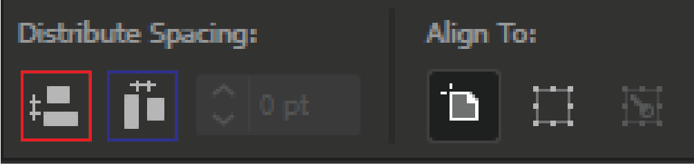
Distribute
Distribute can be used to evenly distribute selected objects between each other.
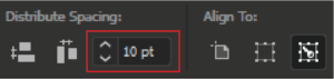
The Distribute settings can be accessed in the Align panel.
Important: make sure to select the objects you want to distribute beforehand.
Red - distribute objects evenly on the vertical axis.
Blue - distribute objects evenly on the horizontal axis.
Align To
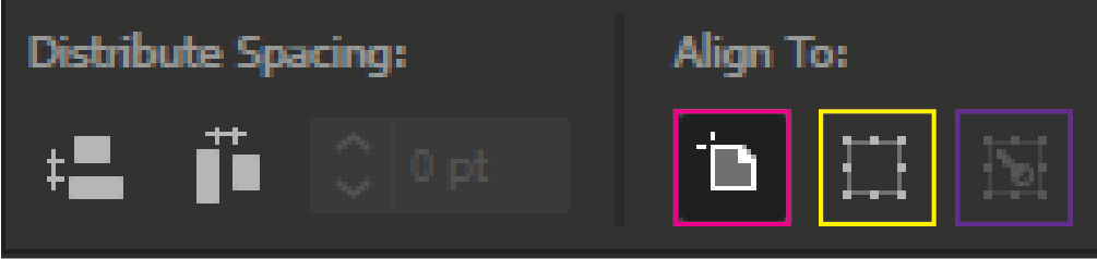
Magenta - aligns/distributes the selected objects to the artboard.
Yellow - aligns/distributes the selected objects based on the bounding box of the selection.
Purple - aligns/distributes the selected objects based on a key object.
With the objects selected and Align To is set to Key Objects, left-click on one of the objects to select it as the reference point.
For example, the red circle on the far right was selected as the Key Object.
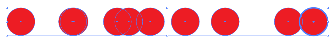
As a result, the selected objects will be distributed horizontally from the right key object.
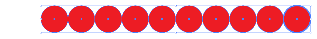
Increasing or decreasing the spacing will change the spacing between each object.

10) Integrating Images
Bitmap images can be imported into Illustrator by either copy-pasting or using Place.
To import an image from your file library, go to File > Place. Select the image and press Place to import the image.
The image will not be placed into the document immediately, you will need to left-click and drag on the artboard to create a frame box for the image to be placed into.
Notes:
- Clipping masks can be used on groups of objects
- Integrating images: clipping mask an image, the whole image will still be in the document.